Understanding the behavior of light as it passes through different optical systems is fundamental in the field of optics. One of the most effective tools for image and analyse these behaviors is the Diverging Lens Ray Diagram. This diagram is essential for students and professionals alike, as it helps in cover how light rays diverge when surpass through a concave lens. By dominate the Diverging Lens Ray Diagram, one can predict the path of light and understand the formation of practical images.
Understanding Diverging Lenses
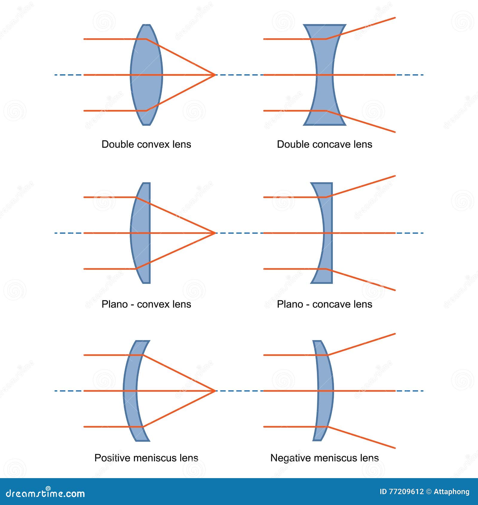
A diverging lens, also known as a concave lens, is a type of lens that causes parallel rays of light to diverge, or spread out, after pass through it. This divergence results in the formation of practical images, which are upright and smaller than the object. The Diverging Lens Ray Diagram is a graphical representation that illustrates this phenomenon.
Key Concepts of Diverging Lens Ray Diagrams
To efficaciously use a Diverging Lens Ray Diagram, it is all-important to understand respective key concepts:
- Principal Axis: The horizontal line pass through the centerfield of the lens.
- Focal Point: The point where parallel rays of light appear to diverge from after passing through the lens.
- Optical Center: The point at the center of the lens where light rays pass through without deviation.
- Ray 1: A ray parallel to the principal axis, which appears to diverge from the focal point after passing through the lens.
- Ray 2: A ray surpass through the visual heart, which continues in a straight line.
- Ray 3: A ray passing through the focal point on the way to the lens, which emerges parallel to the principal axis.
Constructing a Diverging Lens Ray Diagram
Constructing a Diverging Lens Ray Diagram involves respective steps. Here is a detail usher:
- Draw the Lens: Begin by drawing the concave lens and judge the chief axis, focal points, and opthalmic center.
- Draw the Object: Place an object (unremarkably an arrow) on the chief axis to the left of the lens.
- Draw Ray 1: Draw a ray parallel to the principal axis from the top of the object. Extend this ray until it intersects the lens, then draw it diverge from the focal point on the opposite side.
- Draw Ray 2: Draw a ray from the top of the object through the optical heart of the lens. This ray should continue in a straight line.
- Draw Ray 3: Draw a ray from the top of the object through the focal point on the same side as the object. Extend this ray until it intersects the lens, then draw it parallel to the main axis.
- Locate the Image: The point where the diverging rays intersect on the same side as the object is the placement of the virtual image. Draw the image at this point.
Note: Ensure that the rays are accurately drawn to reflect the true behavior of light through a diverge lens. The image formed will always be upright and smaller than the object.
Analyzing the Diverging Lens Ray Diagram
Once the Diverging Lens Ray Diagram is fabricate, it can be analyzed to determine several properties of the image spring. Key properties to study include:
- Image Location: The image is always place on the same side as the object and is virtual.
- Image Orientation: The image is always upright.
- Image Size: The image is always smaller than the object.
Applications of Diverging Lens Ray Diagrams
The Diverging Lens Ray Diagram has numerous applications in optics and related fields. Some of the key applications include:
- Corrective Lenses: Diverging lenses are used in corrective eyeglasses to correct myopia (myopia).
- Camera Lenses: In some camera systems, diverging lenses are used to adjust the battlefield of view.
- Optical Instruments: Diverging lenses are used in several optical instruments to control the path of light.
- Educational Tools: The Diverging Lens Ray Diagram is a valuable educational tool for teaching the principles of optics.
Common Misconceptions
There are several mutual misconceptions about diverge lenses and their ray diagrams. Addressing these misconceptions can help in a punter interpret of the topic:
- Real vs. Virtual Images: Unlike converge lenses, diverge lenses always form practical images. This means the image cannot be projected onto a sieve.
- Image Size: The image formed by a diverge lens is always smaller than the object, careless of the object s length from the lens.
- Ray Behavior: The rays do not really converge to a point; they only appear to diverge from a point behind the lens.
Note: Understanding these misconceptions can aid in accurately interpreting the Diverging Lens Ray Diagram and use the principles of optics correctly.
Practical Examples
To further exemplify the use of the Diverging Lens Ray Diagram, regard the following practical examples:
- Corrective Lenses for Myopia: A person with myopia (myopia) has difficulty seeing distant objects understandably. A diverge lens is used to correct this by diverging the incoming light rays, allowing them to focus correctly on the retina.
- Camera Lens Adjustments: In photography, diverging lenses can be used to adjust the field of view, create it wider and capturing more of the scene.
Advanced Topics
For those interested in dig deeper into the subject, advanced topics colligate to the Diverging Lens Ray Diagram include:
- Thin Lens Formula: This formula relates the object length, image distance, and focal length of a lens. It is particularly utilitarian for calculating the properties of images spring by diverging lenses.
- Lens Maker s Formula: This formula is used to design lenses with specific optical properties, including diverge lenses.
- Aberrations: Understanding the several types of aberrations that can occur in optical systems, include those imply diverge lenses, is crucial for designing high quality optical instruments.
Note: Advanced topics require a potent groundwork in basic optics and mathematical skills.
Comparative Analysis
To better translate the Diverging Lens Ray Diagram, it is helpful to compare it with the Converging Lens Ray Diagram. Here is a comparative analysis:
| Property | Diverging Lens | Converging Lens |
|---|---|---|
| Image Type | Virtual | Real or Virtual |
| Image Orientation | Upright | Inverted or Upright |
| Image Size | Smaller | Larger or Smaller |
| Ray Behavior | Diverge | Converge |
Note: The key conflict lies in the behavior of the rays and the type of image formed.
Conclusion
The Diverging Lens Ray Diagram is an indispensable tool for understanding the behavior of light as it passes through a concave lens. By mastering the construction and analysis of this diagram, one can predict the path of light and understand the formation of practical images. This noesis is important for diverse applications in optics, including corrective lenses, camera systems, and optical instruments. Whether you are a student or a professional, a solid grasp of the Diverging Lens Ray Diagram will enhance your understanding of optics and its practical applications.
Related Terms:
- converging lens ray diagram
- converging lens vs diverge
- diverge lens ray diagram image
- ray diagram by concave lens
- meet lens
- which lens is name diverge